I2C Tools I am Using for the RBOT Project
What I am Working On
I am building out a robotics system that I’ve named RBOT. It’s eventually going to be a product, but first I have to get it’s core built out. And that’s all based on I2C.
Oscilloscope
If you are going to write code for electronics that deals in bits changing, especially with bits changing
relative to other bits changing then you definitely need a scope. You can spend a LOT of money on
an amazing scope but you can get a really decent scope for under $400. I like the
Rigol DS1054Z.
Search the web a bit and there’s some upgrades you can hack yourself, if you want to double it’s bandwidth
from 50MHz to 100MHz. I rarely need more than 2 channels, but when you need it you really need it. I commonly
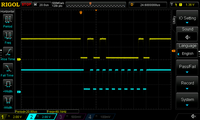
use two channels. Looking at an I2C waveform on the scope looks like this:
Sniffer
Another key tool is an I2C sniffer to passively read the digits from the wire. Luckily I had one in a drawer that was going to get tossed from a company I worked at years ago. I hoard that kind of thing so as I got serious about I2C I pulled it out. Lucky for me after a firmware update it still works! Some tools are just timeless I guess. It’s a Total Phase Beagle and it uses their “Data Center” software. It basically does for I2C what wireshark does for networks.

My Bench
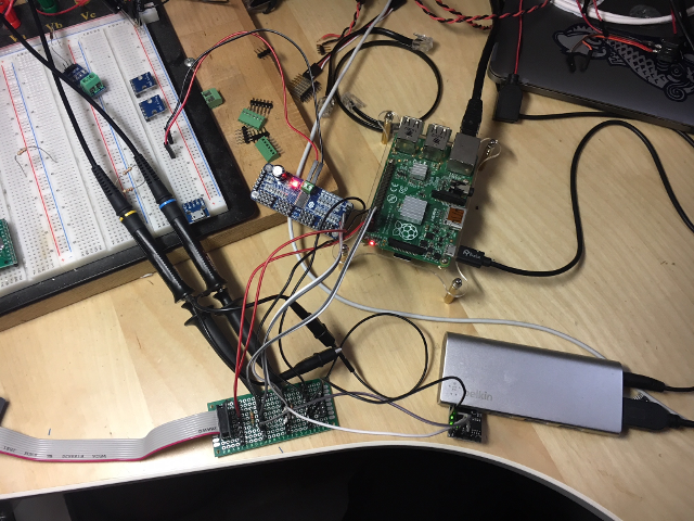
Clearly you need to wire things up. You can use a breadboard but I’ve found that the capacitance of the breadboard could affect things, so I made a rig that has male pins wired in common busses for the clock (SCK) and data (SDA) busses, along with rails for ground and 3V3 - and 4.7kOhm resistors as pull ups on both the lines. I added a 2x5 pin male header wired to match the Beagle and it makes for an extremely easy way to plug it all together and still monitor what’s going on. Here’s what it looks like:
SimAvr
Since one of the parts I am working with is the ATTiny85 that I plan to use an I2C client, I’m really in the dark about what the code on that little AVR processor is doing. There’s no JTAG and only a few spare GPIO pins to blink an LED or something to let me know what’s up. Luckily I just found a nifty looking tool: SimAVR. This tool claims to let me run code compiled for the AVR inside it and simulate being in a real chip. I just installed it (and sent a pull request and will be diving into how to use it next.
Goals
My aim is not only to be able to hang I2C sensors off the bus, but to create my own sensors and actuators using the ATTiny chips. The AVR will sit on the I2C bus and “talk” and it’s other 4 lines can generate PWM, read voltages, drive relays, whatever. These parts are under $2 in qty 1 so they are very affordable. When I’m done I’ll have a whole robotics system that works on I2C, and a set of Golang code to drive all of it over MQTT. I already have a version of this that natively works on the Raspberry Pi called pi-blaster-mqtt but I don’t want to be bound to the RPi so tightly. I have a manual control proof of concept using an XBox Controller too. See goxb_mqtt. Eventually, MQTT will be the network bus and I2C will be the robot bus. Lots of work between here and there to make that real!
![]()
![]()